Hi All,
Can we route more than 15 layers in orcad pcb designer? Is there any limitations?
I not mentioning about auto routing.
Hi All,
Can we route more than 15 layers in orcad pcb designer? Is there any limitations?
I not mentioning about auto routing.
Hi All,
I have a set of scripts.but some of the scripts are not running.Script path clearly set in allegro.men from my own menu name. But it is not working.is there any soluiton?
Hi guys have a question on shapes and lines and trying to figure out an easy way to display the length of these.
When I draw a line and suppose for a second it is 2 inches long after the line is complete how can I measure the length of the line by perhaps clicking on it or other ? "The ruler works ok but if the line is a meandering type then the ruler dont work so good"
Same thing again with shapes. Suppose I have 3 shapes that are each 1" long by .250" wide. I connect the ends of the shapes and then edit them so they look like mitered transmission lines. In otherwords the 3 shapes are now combined into one to say look like an L. Does anyone know of a good way to measure these ?
On the shapes I again can use the ruler by clicking point to point along each section of the shape until my destination is reached or I can add a line on a different layer that follows the path of the shape to get the total length but I am curious if there is a better way to do this.
It would be neat if Allegro had a way of figuring out the length of lines and shapes just by clicking on it...
Thanks Scott.
Hi @all!
I have a problem creating keep outs with individual outlines. I do have a shape basicly circular - it look a bit like a gearwheel. I do have that shape as an dxf so i can use the import function of allegro. But (correct me if i'm wrong) i have to use a filled shape for creating a keep out.
This far i found just one way to create that: By importing a filled shape from the dxf. But in that case allegro is creating the shape filled with triangles.
For the keep out it would work, but it would not look nice. But for a second area this is quite a problem: I want to create areas with a height restriction. I was told that i should import the area to the "Place_Bound_Top" layer and set the properties of the area accordingly. But if the area is filled with those triangles i would have to set the height restriction for every single triangle (ok, i know, i can set the parameters for all triangles at once - but i still have to select every single triangle).
I also tried to create the shape with the allegro tools (-> "shape add"), because i figured that those shapes would be filled "solid". But i'm not able to create the shape i need with the allegro toolset.
Is there a way to get rid of the triangles? Thanks in advance!
Hi All,
I am using Allegro 16.5 xl. license.
I need to place few components on internal layers. how should i use the embedded componenet placement .
Also, pls let me know how can it be done in PCB itself (without schematics changes)
thanks
Bala R
Hello, I'm new to Cadence, coming from Altium. I'm using Allegro Design Entry HDL and PCB Editor, rev 16.3.
As part of the new design and "new to designing with Cadence" process, I am creating parts for our library and I'm having some trouble with a TI SON part that includes a thermal pad or power pad. Here is a snap shot from the TPS6120:
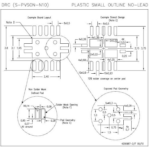
At this point, I've made the pads in the padstack editor (but made them rectangles since I didn't know how to make it a rect at one end and rounded at the other) and used the symbol creation wizard to make a SOIC. To make the thermal pad I placed a filled polygon on the Etch/top layer and it is one large pad with the outline like above.
Question: How do turn my filled polygon into a ground pin (or should I not?) and how do I add the soldermask layer to something I've drawn like this?
Question: How do I add vias to my footprint? My plan was to create the via in the padstack editor then place them in the appropriate places but I have some confusion as to whether the pad/via structure is just supposed to sit there dangling or if it should be assigned a pin # (ground).
I did search the forum and came across the thread Thermal Pad Shape with Vias In it a poster mentions that he makes these pads using multiple surface mount style pins. I think I can figure out how to do this but I'd appreciate any tips on setting up the tools and pads so that things are properly done.
Picture of the pad made from pins:

Sorry in advance if this is a simple question easily answered elsewhere.
I am creating a PCB that needs to have different sized layers. Basically the stackup is as follows:
Die
LTCC
Interposer
routing/signal layers (dielectrics and conductors)
The die has a footprint, but the LTCC and the interposer are significantly smaller in size than the circuit board on the bottom. Is there a way to model this in Allegro? Thanks for any help. Obviously this is a simple description of the project.
Hi,
Is there a way to get rid of the pop up tool tip that shows the full library path when I place my cursor over either a listed library or a listed part in the Place Part dialog? I find this pop up extremely anoying and I've looked at all the options and customizations I can find to get rid of it with no luck. Thanks.
Robert
Hi all,
I need to add a line wich has no rounded end to my PCB. Is there any option to select between rounded and not rounded end, when you drop you left mouse button after drawing the track ?
Many thanks for your help and kind regards !
Hi to all,
how I can create a new property on symbols like "COMMENT", or "VOLTAGE " on nets ?
I use a netlist Telesis to import data so I'd like to have more info like Max Current for each net.
So I'd like to have:
$NETS
....
$A_PROPERTIES
MAXAMPERE 5; NETNAME
and then find the property MaxAmpere setted on Orcad DB (with property VOLTAGE this work fine).
or
on symbol, I'd like to have a property Note to storage the Designer Note about that component.....and so on
Thanks :-)
Mirko
I am trying to interlinkCAM350 with Allegro PCB editor.
While enabling Cross Probe Allegro in CAM350 its giving message as "start Allegro and the DstCAM350() script. "
can anybody tell me about this script file and the procedure to interlink these tools?
Hi!
I'm new to PCB Design. So I'm truing to do my fisrt PCB. I have made my schematics but I can't create a netlist. I select "PAGE1", that is my schematics not my project. I click on Create netlist and Accept. But after a few second the program show me that "ERROR(OrCAP-32042): Netlister failed. Please refer to Session Log or netlist.log for details".
Can anybody help me, please??
Thanks,
Oriol
Hi All,
I have a problem while doing the routing. Attched the snap shot. If i reroute the net problem sloved. is there any easy way to slove this problem. I am using allegro 16.3

Thanks,
Selva
I am new to PCB Editor and I am learing how to back annotate into Capture CIS. I am getting the following error :
#1 ERROR(ORCAP-36055): Illegal character in \df12(5.0)-36dp-0.5v.normal\.
#2 ERROR(ORCAP-36055): Illegal character in DF12(5.0)-36DP-0.5V.
#3 ERROR(ORCAP-36055): Illegal character in \sm02b-srss-tbt (lf) (sn).normal\.
#4 ERROR(ORCAP-36055): Illegal character in SM02B-SRSS-TBT (LF) (SN).
#5 ERROR(ORCAP-36018): Aborting Netlisting... Please correct the above errors and retry.
So these illegal characters are in the value property. How do I change the value of the component in Allegro PCB Editor?
Hello
Well I have install on my computer the Allegro 16.3 and recently I installed PAD 9.3 and maybe that was a terrible mistake, because Capture from Allegro crash and the Pad Designer too.
So I fix the problem with Capture changing the variable "path" but now I find out that Pad Designer doesn't save the pads T_T and the only error is "Save error: -3000289"
Someones nows about this problem about PADS and Allegro in the same PC? and how to fixes?
I really need bouth software.
Thanks for your time.
Hi,everyone.
I’m simulating a ‘grid-connected’ PV system.
1) 1) Here is the ‘.cir’ file I want to simulate.
* NODES
* (0) Reference
* (1) Irradiance profile input
* (3) PV generator output
* (4) Inverter Input
* (6) Inverter output
* (20) PV generator current at the maximum power point
* (30) PV generator voltage at the maximum power point
** PV generator
.include generator_beh.lib
xgenerator 0 1 43 3 45 46 47 20 30 generator_beh params:
+ iscmr=5.2, coef_iscm=0.13e-3, vocmr=21.2, coef_vocm=-0.1,pmaxmr=85,
+ noct=47,immr=4.9 , vmmr=17.3, tr=25, ns=36, nsg=2 npg=3
** Irradiance and temperature profiles
.inc aprilmicro.stl
vmesur 1 0 stimulus Virrad
vtemp 43 0 dc 12
** Blocking diode
d2 3 4di ode
.model diode d(n=1)
** inverter
.inc inverter7.cir
xinvert 40 6 20 30 inv params: nf=0.9
** grid
.inc grid.cir
xgr1 6 0 grid
.tran 1ms 0.14s 0 1u
.probe
.end
2) The output file says that are some ERRORS. Here is the ‘.out’ file.
**** 10/12/12 17:43:57 ******* PSpice Lite (April 2011) ******* ID# 10813 ****
* NODES
**** CIRCUIT DESCRIPTION
******************************************************************************
* (0) Reference
* (1) Irradiance profile input
* (3) PV generator output
* (4) Inverter Input
* (6) Inverter output
* (20) PV generator current at the maximum power point
* (30) PV generator voltage at the maximum power point
** PV generator
.include generator_beh.lib
**** INCLUDING generator_beh.lib ****
* BEHAVIOURAL MODEL OF A PV GENERATOR
* INPUT PARAMETERS:,AM1.5 JSCMR,AM1.5 VOCMR,AM1.5 PMAXMR
* AM1.5 VMMR,AM1.5 IMMR, CURRENT TEMP COEFF.,VOLTAGE TEMP.COEFF,
* NOCT, REFERENCE TEMPERATURE
* NODES
* (400) REFERENCE
* (401) INTERNAL NODE
* (402) INPUT, IRRADIANCE
* (403) INPUT, AMBIENT TEMPERATURE
* (404) OUTPUT
* (405) OUTPUT, (VOLTAGE) VALUE=SHORT CIRCUIT CURRENT(A) AT
* IRRADIANCE AND TEMPERATURE
* (406) OUTPUT, OPEN CIRCUIT VOLTAGE AT IRRADIANCE ANDTEMPERATURE
* (407) OUTPUT, (VOLTAGE) VALUE=CELL OPERATING TEMPERATURE(
C)
* (408) OUTPUT, MPP CURRENT
* (409) OUTPUT, MPP VOLTAGE
--$
ERROR -- Missing node
.subckt generator_beh 400 402 403 404 405 406 407 408 409 params:
+ iscmr=1, coef_iscm=1, vocmr=1, coef_vocm=1,pmaxmr=1,
+ noct=1,immr=1 , vmmr=1, tr=1, ns=1, nsg=1 npg=1
ev402 410 400 value={if (v(402)>0.1, v(402),0.1)}
girrad 400 401 value={v(410)/1000*(npg*iscmr+npg*coef_iscm*(v(407)-25))}
eiscm 405 400 value={v(410)/1000*(iscmr+coef_iscm*(v(407)-25))}
evocm 406 400 value={if (v(405)>1e-11, (vocmr+coef_vocm*(v(407)-25)+8.66e-5*
+ (v(407)+273)*log(v(405)/(iscmr))),0)}
etcell 407 400 value={v(403)+(noct-20)/800*v(410)}
gidiode 401 400 value={npg*v(405)/(exp(v(406)/(ns*8.66e-5*(v(407)+273)))-1)*
+ (exp(v(401)/ (ns*nsg*8.66e-5*(v(407)+273)))-1)}
rsg 401 404 {nsg/npg*((vocmr/(iscmr)-pmaxmr/(iscmr**2*(vocmr/(ns*0.0258)-log
+ ((vocmr/(ns*0.0258))+0.72))/(1+vocmr/(ns*0.0258)))))}
.func frsg() {nsg/npg*((vocmr/(iscmr)-pmaxmr/(iscmr**2*(vocmr/(ns*0.0258)-log
+ ((vocmr/(ns*0.0258))+0.72))/(1+vocmr/(ns*0.0258)))))}
gimg 400 408 value={npg*(immr*v(410)/1000+coef_iscm*(v(403)-25))}
rimg 408 400 1
evmg 409 400 value={if (v(410)>0.1, nsg*(ns*8.66e-5*(v(407)+273)*log(1+(v(405)-
-------------------$
ERROR(ORPSIM-16367): End of expression not seen
+ (ns*8.66e-5*(v(407)+273)))-1))-v(408)*frsg/nsg),0)}
.ends generator_beh
-----------------------------------------------------$
ERROR(ORPSIM-16367): End of expression not seen
.ends generator_beh
-----------------------------------------------------$
ERROR(ORPSIM-16500): Missing node
-----------------------------------------------------$
ERROR(ORPSIM-16499): Missing .ENDS in .SUBCKT
**** RESUMING "EXAMPLE 8.1.CIR" ****
xgenerator 0 1 43 3 45 46 47 20 30 generator_beh params:
+ iscmr=5.2, coef_iscm=0.13e-3, vocmr=21.2, coef_vocm=-0.1,pmaxmr=85,
+ noct=47,immr=4.9 , vmmr=17.3, tr=25, ns=36, nsg=2 npg=3
** Irradiance and temperature profiles
.inc aprilmicro.stl
ERROR(ORPSIM-15347): Cannot open input file D:\Program Files\OrCAD 16.5 Lite\tools\pspice\aprilmicro.stl.
ABORTING
SIMULATION
**** 10/12/12 17:43:57 ******* PSpice Lite (April 2011) ******* ID# 10813 ****
* NODES
**** JOB STATISTICS SUMMARY
******************************************************************************
Node counts:
Top level (NUNODS) = 1
External (NCNODS) = 1
Total (NUMNOD) = 0
Total device count (NUMEL) = 1
Capacitors (C) = 1
Number of subcircuits (X) = 1
Matrix statistics:
Matrix size (NSTOP) = 0
Initial no. elements (NTTAR) = 0
No. elements w/ fillin (NTTBR) = 0
No. fillins (IFILL) = 0
No. overflows (NTTOV) = 0
No. LU operations (IOPS) = 0
Percent sparsity (PERSPA) = 0.000
Analysis statistics:
No. total time points (NUMTTP) = 0
No. rejected time points (NUMRTP) = 0
No. iterations (NUMNIT) = 0
Runtime statistics: Seconds Iterations
Matrix load = 0.00
Matrix solution = 0.00 0
Readin = 0.00
General setup = 0.00
Setup = 0.00
DC sweep = 0.00 0
Bias point = 0.00 0
AC and noise = 0.00 0
Total transient analysis = 0.00
Output = 0.00
Overhead = 0.00
Total job time = .25
3) Below is the information shown at the OUTPUT WINDOW
--------------- INFO(ORPROBE-3210): Simulation Circuit File: EXAMPLE 8.1 ---------------
INFO(ORPROBE-3183): Simulation running...
* NODES
Reading and checking circuit
Missing node
ERROR(ORPSIM-16367): End of expression not seen
ERROR(ORPSIM-16367): End of expression not seen
ERROR(ORPSIM-16500): Missing node
ERROR(ORPSIM-16499): Missing .ENDS in .SUBCKT
ERROR(ORPSIM-15347): Cannot open input file D:\Program Files\OrCAD 16.5 Lite\tools\pspice\aprilmicro.stl.
ERROR(ORPSIM-15347): Cannot open input file D:\Program Files\OrCAD 16.5 Lite\too
Run aborted
Circuit has errors ... run aborted
See output file for details
INFO(ORPROBE-3188): Simulation aborted
All,
When running a standard drill legend, I have one drill that says i have four of instead of two. I deleted one from the board, ran another drill legend and it reported I had two rather than one. I deleted the remaining hole, ran the legend again, no hole. Put the holes back and it reported the original four. Checked the padstack for any anomaly but it was okay. Anyone see this before?
Thanks
Hello all - I use PCB Editor on 3 different machines at various times of the week. I have my user preference for the display of my cursor set to "infinite". On two of the three machines I experience a "ghosting" of the cursor as I move it across the screen. A remnant of the cursor display is left until I pan or zoom. Any ideas what might be causing this? I'm guessing my graphics card. Thanks in advance.