Quantcast
Channel: Cadence PCB Design Forum
Viewing all 5525 articles
Browse latest View live

Allegro grid snap

$
0
0

For some reason Allegro is forgetting that I have grids turned on. When I first open Allegro it works for a little, while then it just decides it no longer wants to follow the grids. I shut it down and restart and it works for a little while then off again. I know this is probably something obvious but I just can't find it.

Thanks


Preserve around BGA from other symbol placement

$
0
0

Hi,

I am going to use a heat sink with a clips on my BGA and I need to prevent other parts to come closer than a specified distance. I have placed a rectangle on "Package Keepout/Top" so other parts can't come into this region. However, I have a problem, that is the BGA itself is in this region and DRC generates error. How I can exclude this part from this rule/constraint? Is there another way that I can place a guard around my BGA?


Comments are welcome.

Hossein

BNC Schematic Symbol (2 pins) to PCB Footprint (5 pins) best practice

$
0
0

Hello Everyone,

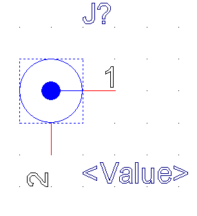
I have a BNC connector that physically has 5 pins.  A typical BNC schematic symbol only has two pins.  In the past I've simply made a new schematic  symbol with 5 pins, four of which are ground, and called it a day (schematic symbol pin count matches pcb footprint).

Has anyone figured out how to use a 2 pin schematic symbol for the 5 pin part?  I'd like to clean up future schematic and avoid having the extra pins.

I typically shy away from having a schematic symbol pin count differ from the footprint but am willing to make an exception in this case. 

Would you leave it as a 5 pin schematic symbol and call it a day?  Would you "clean" it up and somehow make the BNC connector have 2 pins in the schematic?  If so how?

BNC_2pin, BNC_5pin, BNC_part

Thanks for any inputs.

Netlist error

$
0
0

I've gotten the following error when generating a netlist on a schematic.  It goes away if I delete the part in question, but comes back if I add that part back to the schematic.  An earlier version of the schematic with the same part goes through the netlist creation without any errors.  Any idea what is causing the problem?

Thanks,

John

(project name/path and part name replaced with generic names to remove proprietary information)

Loading... C:\...\ALLEGRO/pstxnet.dat

packaging the design view...#228 ERROR(SPCODD-228): Cannot package the following primitive instance in any section of the physical part 'MOSFET_PACKAGE_MOSFET'.

Primitive Instance: @\schematic post review\.schematic1(sch_1):ins2777027@orcad_parts.\MOSFET.normal\(chips) (MODULE: SCHEMATIC POST REVIEW; PART: MOSFET)

The primitive instance has pins which does not match the section definition in chips.prt. Check the pin definitions for each section in the chips.prt file. Regenerate the netlist and rerun packager.

#53 ERROR(SPCODD-53): Packaging cannot be completed because packaging has encountered a null object ID. The design may not have been saved correctly. Save the design before packaging.

ERROR(SPCODD-391):

Reference Designator: Q201. Could not pack schematic instance @\schematic post review\.schematic1(sch_1):ins2777027@orcad_

parts.\MOSFET.normal\(chips) (MODULE: SCHEMATIC POST REVIEW; PART: MOSFET) in sections.

#53 ERROR(SPCODD-53): Packaging cannot be completed because packaging has encountered a null object ID. The design may not have been saved correctly. Save the design before packaging.

Orcad Capture Market Place

$
0
0

Hello

 I am trying to download Orcad capture apps from capture market plus , when I use my community account log in it’s not taking


As well when I try for new account creation its saying not supported in your country .


User defined properties

$
0
0

Hi,

I have created a user defined property, added it to my allegro.cfg file, and successfully imported it into PCB Editor by referencing this discussion:

http://community.cadence.com/cadence_technology_forums/f/27/t/10835

My goal is to define a "silkscreen" layer for testpoints, connectors, components, etc. to be linked to that component for easy viewing once the board is manufactured.

The problem is once my "silkscreen" property is created via the "Display > Properties..., Graphics tab" menu in PCB Editor, it shows up on both layers. I only want it to show up on the layer in which the through hole component was placed. Is this possible?

Thanks!

Aric

Design Setting

$
0
0

Hello everyone,

can anyone give a description about the "design setting" in parameters?

I didnt found any application note yet. As i know there are some points in "Design Parameter Editor"

What is inclouded?


Best regards.....

Plotting option error occured trying took printout

$
0
0

Hi..

For my finished my board i  try to print the error occurred as "There is not enough memory for this operation". The window is also get exits. 

I had changed the grid option too,then checked the extent widths of X & Y respectively. Does the height and width does to been get changed or not.

I had tried many times to took print out, but i can't?? 

Thanks  in advance..


PCB plot in Print Manager problem

$
0
0

Hello,

this is the first time I print a PCB with Print Manager and I Have a strange problem.

I select "Post Process Settings" and then in the Layer spreadsheets I select Plot to Print manager in order to create a PDF of the selected layer.

The print preview is ok but the PDF has a different copper pour aspect: around vias and round pads che copper pour has a wavy ondulated contour. This happens also with a different PDF printer driver so I suppose is a setting problem of ORcad layout. Can anyone help me?

Best regards.

Integrate PSpice netlist into Capture schematic

$
0
0

Hello,

How to integrate PSpice netlist in Captureschematic.
I've tried 2 appoaches:

  • using Hierarchical block
  • using Library part


In both cases I failed: via hierachical block ... the port names exposed in PSpice netlist subcircuit don't appear in schematic, 2nd approach solicits Model Editor, where there is no option for .SUBCKT-type models (at least I didn't find how to do it), only templates such as diodes, bipoalires, opamps, etc.

My PSpice netlist is generated by 3rd-part tool and doesn't match any template, proposed by Model Editor.

How to proceed.

Thanks in advance.

Pavel

PSMPATH and subdirectories

$
0
0

Is it possible to just specify a directory for footprints and allow the software to search all the subdirectories and not have to list each one ?

Routed Trace not visible Dynamically

$
0
0

Hi,

If i draw a trace, or move an object or do anything in cadence allegro 16.5, nothing happens, but if i zoom in/out, then its already visible what i have done.

so during editing, i cant see what i am editing, only after zoom...
screen is not real-time. why is it?
how can i make it visible during editing?
there wasnt such problem with allegro 15.7. is it some opengl bug? i have intel graphics, 965chipset.

How to arrange my board design based on the A4 page size

$
0
0

Hello:

I wanna arrange ten board designs on A4 page.

How to adjust the board design coordinate and put the ten designs on the same page in the pcb editor.

Concept HDL Settings

$
0
0

I'm looking for a way to preserve my ConceptHDL settings (i.e. grid sizes, page border symbol, custom variables, etc..).  During the instantiation of new projects these settings return to default, and I would like to have them persist across all our projects.  Is there a file that I can add/modify to obtain this goal?

Thanks much, Tom

Cross probe parts and move them together

$
0
0

I have my parts placed using quick place. I want to be able to select a group of parts in Orcad , have them selected in Allegro and then move those parts that are located randomly  to a small group next to each other.  


Unplacing more than one component

$
0
0

I can select one component and un place it with the RMB Unplace component.  How do you unplace multiple components ? That RMB does not have unplace button.

Get value of component by SKILL

$
0
0

Dear All,

When select a component on drawing then choose menu Display/Element, i can see value of component  on Show Element  window as below:

Properties attached to component definition
    TOL               = 10
    VALUE             = .01UF

How i get value of component (0.01UF) by using skill code

Thanks,

Hung

Orcad Capture Footprint property and Allegro .dra package symbol

$
0
0

In capture when I right clicked the component and under the footprint property can I put down the path to the .dra footprint from allegro?

If not?  the second way to associate the allegro footprint would be "Place manually" and bring in the allegro footprint that way?

Routing of DDR2/DDR3 Memory

$
0
0

According to JEDEC DDR2/DDR3 layout guidelines, the routing of signals has to follow certain topologies, but can I disregard those and just put the delay skew between datelines and differential signals into the constraint manager. Also I constraint all the DRAM signals with 50 ohm impedance as to match the impedance.  

Once I put in those contrasts(impedance, delay skews,  setup/hold time) and I let the auto router to take care of everything.

Would this approach work without following the JEDEC recommended topologies?

WARNING(ORNET-1119): No PSpice Template for...

$
0
0

Hello,

I wanted to use libraries from older ver. ORCad (16.2) in new one because I haven't find two elements (BD 139 and BD140). I added older libraries but now appears problem from the title. Is there chance to use older olb files in newer Orcad ? Or maybe are there somewhere these elements compatible with ORCad 16.6 ?

Best regards

Dom Dom

Viewing all 5525 articles
Browse latest View live


<script src="https://jsc.adskeeper.com/r/s/rssing.com.1596347.js" async> </script>