Quantcast
Channel: Cadence PCB Design Forum
Viewing all 5525 articles
Browse latest View live

I Cannot see the thermal relief and antipad on my GND plane.

$
0
0

 Hi,

    I am now using Cadence 16.5 SPB for my PCB design.  Managing to layout a 6-layered board, I have set my GND Plane as a negtive artworked.  I tried to fill this GND Plane with a GND-assigned dynamic copper.  However, to my surprise, I could not see the thermal relief and antipad in this plane.  The status of shape is already a "smoothed" one.  I don't know why the thermal pad and the antipad are invisible (or non-exist) in my design.  Without them, by no means could I generate a proper artwork for manufacturing.

   Could you help me?


Naroah

Apr/07/2014


REG: FIND WINDOW VISIBILITY IN ORCAD CAPTURE16.3

$
0
0

 Hi,

How to  set the visibility of the attached window in Orcad capture16.3.

By mistake I closed this window (Find window)  , I tried lot unable to set the visibility.

If anybody knows pls. help me 

Regards,

Girish 

quality check list

$
0
0

what is meant by package keep off & route keep off in quality check list...?Thakyou in advance...

[SOLVED] Problem with two versions of CADENCE

$
0
0

Hi Everyone,

 I recently upgrade my Hard drive into a bigger one from 80 GB to 320G, everything was fine, basically I backup and clone the OS(windows XP) and the installed programs which include CADENCE 16.2 as well. Everything is working perfecrt, But recently we decide to upgrade to CADENCE 16.6 due to many designers are using CADENCE 16.3 and higher. The problem is that I installed CADENCE 16.6 and everything look normal, but there is a problem and it is giving me a error messages on windows. Maybe is because I update the hard drive and it mess up with the register or something. I used the "Cadence SPB switch release" and then, When I try to open DESING ENTRYCIS (ORCAD) the following message apperas "Capture.exe - Entry Point Not Found,  X  The procedure entry point ?find@SBString@@QEHPBDH_N@Z cold not be located in the dynamic link library SBaseMD_sh.dll". And when I try to open allegro this message show up "allegro.exe - Entry Point Not Found, X The procedure entry point obSearch could not be located in the dynamic link library _cadencehelp.dll.". I tried to re-install all the application again and again, and I am still getting the same error. Please could anybody help me to fix this issue. I really wnat to try the CADENCE 16.6, because I read the new features that it has, and they look awsome.

Thanks in advance for the help.


Regards.


Hide pin name in OrCAD Capture 16.2

$
0
0

 Hi,

I'm making a customized symbol in Capture, but having problem hiding the pin name while showing the pin itself.  What I'm trying to do is making a symbol similar to the VCC/CAPSYM that is included in OrCAD Capture, in which I have the option to display or to hide the name (VCC).  For some reason, I'm not able to do this in my own symbol.  If I change the pin type to POWER, I can hide the pin and the name at the same time, however, it's not what I want.  I want to hide/show the pin Name instead of the pin itself.

Thanks for answering my question.

SPLBPD-506

$
0
0

Hi All,

Using 16.6-S026. Still going up the learning curve on this tool. I'm modifying a schematic that was generated by someone else.

My problem is that when I try to add a component from the reflib, not all components are available (saw_rx_single). I opened

part developer for this part and got this message:

Cell 'saw_rx_single' : For logical part SAW_RX_SINGLE, pack type LCC is missing in chips.prt but present in the part table file. The default package will be assigned in chips.prt during packaging. If this is not desired, specify the pack type on the General page of the Package Editor.

I couldn't see a problem in the chips.prt file. In the part table file the PACK_TYPE column is empty. How can I fix this?

Thanks!

Bob

Default Toolbars in Capture CIS

$
0
0

Does anyone know how to set which toolbars are visible by default in Capture?  I would like the 'Draw' toolbar to be visible by default everytime I open the schematic editor, but have found no setting that sticks between the times I start the tool.  The Capture, Part Manager, and Search toolbars are handily checked when I open the Tools->Customize dialog, but checking the Draw box only holds while I'm using the tool.  

Is this a Capture.ini setting that I'm missing?  


This is nearly as frustrating as being forced to go through the exact same print setup steps everytime I want to save a PDF snapshot. 


Jerry 

Moving a set of object by fixed distance in Allegro

$
0
0

 Dear All,

I want to move a set of objects ( combination of trace,polygons.Symbols etc) by a fixed distance.

I am able to move only a symbol by fixed distance by type ix 'd' or by iy 'd'.

But to move a set of objects what can be done ?

Kind Regards,


OrCad 16.6 Lite

$
0
0

Hi all,

I've just tried OrCad 16.6 lite version. I used capture cis to design a simple circuit, but I wasn't able to run Pspice because the assosiated toolbar was unabled.

Can anyone help to this?

Thanks in advance.

Why can't I login to this forum with IE?

$
0
0

Just a repetitive problem I'm having.  My Win7 64-bit PC and IE10 will not let me log-in to the Cadence forum.  No errors, block notices or anything.  It just won't do it.  Log-in attempts spend a few secs "waiting circle" and then return me to the login screen.

Chrome on the other had has no problem from the same PC (i.e. I'm here now).

 Anyone got any Microsoft clues?

Regards, 

custom menu

$
0
0

We are using Cadence 16.5 & I want to create custom menu for our CAD group.

First I added menu in allegro.men (...folder\share\pcb\text\cuimenus),

POPUP "&CAD Menu"
BEGIN
MENUITEM "&Bead Probe", "BeadProbe.il"
MENUITEM "set_refdes.il", "srd save"
END

I even added load("BeadProbe.il") and load("set_refdes.il") in allegro.ilinit

second, copy the Skill files to this location C:\Cadence\setup\pcbenv\skill

Now, when I open the database it loaded the CAD Menu, but when I select the command it show.

E- Command not found "srd save"

I tried both of the command and none of them is working.

Any advice would be greatly appreciated


Can't choose directory for netlist files

$
0
0

When netlisting from Design Entry CIS for the PCB editor, the dialog box is drawn with the right side of the box including the browse button for the Netlist Files Directory obscured.  It's a major painto have to type an absolute path into the box which not coincidentally doesn't show the whole path.   Resizing the window does not cure the issue, nor does changing tabs to try to force the window to redraw.  Another consequence is that the radio button label for Place Change Components Never is obscured in the same manner.

This is a new behavior since installing 16.6 on Win7 64 bit. 

 Is this a known problem?

The screenshot below shows the result after dragging the window wider.


Differential Pair routes with No Gap

$
0
0

Hi,

I'm using OrCAD PCB Designer and have created differential pairs. When I manually route the pair, the gap between traces is always zero no matter what I set the gap to in the contraints manager. I'm fairly new to this tool so I'm getting a littel frustrated why it does this. I even found another posting that some provided a .brd design with a diff pair and its own CM settings. When I deleted the traces to then reroute them, I found the same problem, the trace gap went to zero! Is this a license limitation or am I missing something? I've created CSet spacing parameters in the CM.

Thanks for any help that someone might be able to provide.

 -KC 

basics of thermal pad / power pad footprint creation

$
0
0

Hello, I'm new to Cadence, coming from Altium. I'm using Allegro Design Entry HDL and PCB Editor, rev 16.3.

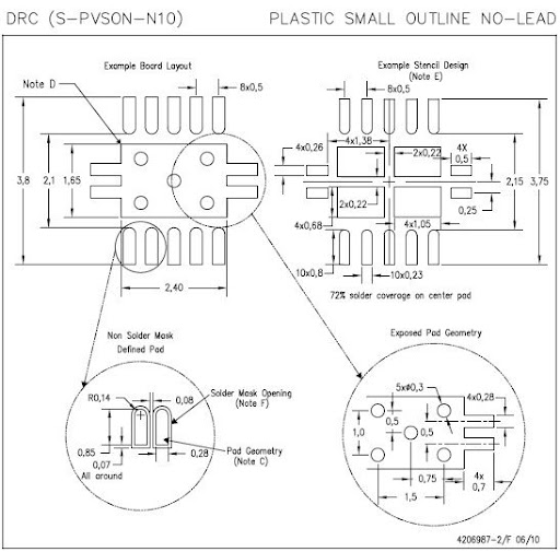
As part of the new design and "new to designing with Cadence" process, I am creating parts for our library and I'm having some trouble with a TI SON part that includes a thermal pad or power pad. Here is a snap shot from the TPS6120:

 TI TPS61202 Footprint

At this point, I've made the pads in the padstack editor (but made them rectangles since I didn't know how to make it a rect at one end and rounded at the other) and used the symbol creation wizard to make a SOIC. To make the thermal pad I placed a filled polygon on the Etch/top layer and it is one large pad with the outline like above.

Question: How do turn my filled polygon into a ground pin (or should I not?) and how do I add the soldermask layer to something I've drawn like this?

Question: How do I add vias to my footprint? My plan was to create the via in the padstack editor then place them in the appropriate places but I have some confusion as to whether the pad/via structure is just supposed to sit there dangling or if it should be assigned a pin # (ground).

I did search the forum and came across the thread Thermal Pad Shape with Vias In it a poster mentions that he makes these pads using multiple surface mount style pins. I think I can figure out how to do this but I'd appreciate any tips on setting up the tools and pads so that things are properly done.

Picture of the pad made from pins:

pad of pins

specctra quit unexpectedly with an exit code of 5

$
0
0

Hi guys, yesterday when I ran the command of 'automatic router ' in PCB Editor, the message ' specctra quit unexpectedly with an exit code of 5 ' was shown on the screen and I was confused , because I never seen it before.

 Then I looked the Specctra Log file and there are several error message shown below:


# <<WARNING:>> Potential non fixed positive shape alignment with the host CAD system exists.

#              Allegro PCB Router does not perform any operations to remove or identify slivers and isolations.

#              If the host CAD system performs such an operation, the user may experience unrouted

#              or DRC alignment issues.

#              The user must perform final unrouted/DRC validation within the host CAD system.

# <<ERROR:>> Error in file D:/BIT work/MB7K01/PCB\MB7K01.dsn, line 19668: token 5 = Orphan_net

# (content):   (wire (net Orphan_net) (type route))

# <<ERROR:>> Parser: Unrecognized token net while parsing shape 


I have no idea about  " line 19668: token 5 = Orphan_net "

Can anyone help me to solve it please?

 Thank you very much!


how create a ".cir" file in Orcad 16.3

$
0
0
Hello, 
I would like to create a "cir." file in Orcad 16.3 but I'm a little lost, is that you can help me? 
is and what you can tell me how to change the number of output bipolar transistors, ie, I find in the software transistors 3 terminals (EBC), while I want to add the substrate channel but I do not know how. and when I change the netlest and I run the simulation it removes all the changes I did. 
Thank you for your help.

[DE HDL] Update all symbols in schematics

$
0
0

Hi,

I want to update all the symbols in the schematics that have been changed in the library. I can do it with 1, 2... components by right-click > Version > 1 but I don't know how to do it automatically with all the components of same part.

 Thanks for your help.

PSpice Model for a 4017 Decade Counter?

$
0
0

 I found the following model code for a CD4017B decade counter, but it doesn't work. I'm getting an error as seen in the attachment. The model code I found is:

*---------
* CD4017B CMOS COUNTER/DIVIDER
*
* CMOS INTEGRATED CIRCUITS DATABOOK, 1983, RCA SOLID STATE DIVISION
* NH 9/8/92      REMODELED USING LOGICEXP, PINDLY, CONSTRAINT DEVICES
*
.SUBCKT CD4017B CLK_I CLKINHIBIT_I RESET_I O0_O O1_O O2_O O3_O O4_O O5_O O6_O
+               O7_O O8_O O9_O CARRYOUT_O
+ OPTIONAL: VDD=$G_CD4000_VDD VSS=$G_CD4000_VSS
+ PARAMS: MNTYMXDLY=0 IO_LEVEL=0
*
U17BBUF BUF VDD VSS
+ CLK_I CLK
+ D0_GATE IO_4000B_ST IO_LEVEL={IO_LEVEL}
*
U17BLOG LOGICEXP(13,16) VDD VSS
+ CLK CLKINHIBIT_I RESET_I Q1 Q2 Q3 Q4 Q5 Q1BAR Q2BAR Q3BAR Q4BAR Q5BAR
+ CLKINHIBIT RESET CLOCK O0 O1 O2 O3 O4 O5 O6 O7 O8 O9 CARRYOUT TOQ3 RST
+ D0_GATE IO_4000B IO_LEVEL={IO_LEVEL}
+
+ LOGIC:
+
* BUFFERS
+   CLKINHIBIT = { CLKINHIBIT_I }
+   RESET = { RESET_I }
+
* OUTPUT ASSIGNMENTS
+   CLOCK = { ~(~CLK | CLKINHIBIT) }
+   O0 = { Q5BAR & Q1BAR }
+   O1 = { Q1 & Q2BAR }
+   O2 = { Q2 & Q3BAR }
+   O3 = { Q3 & Q4BAR }
+   O4 = { Q4 & Q5BAR }
+   O5 = { Q5 & Q1 }
+   O6 = { Q1BAR & Q2 }
+   O7 = { Q2BAR & Q3 }
+   O8 = { Q3BAR & Q4 }
+   O9 = { Q4BAR & Q5 }
+   CARRYOUT = { Q5BAR }
+   TOQ3 = { ((Q1 & Q2) | (Q2 & Q3)) }
+   RST = { ~RESET }
*
UFF DFF(5) VDD VSS
+ $D_HI RST CLOCK Q5BAR Q1 TOQ3 Q3 Q4 Q1 Q2 Q3 Q4 Q5
+ Q1BAR Q2BAR Q3BAR Q4BAR Q5BAR
+ D0_EFF IO_4000B
*
U17BDLY PINDLY (11,0,4) VDD VSS
+ O0 O1 O2 O3 O4 O5 O6 O7 O8 O9 CARRYOUT
+ CLOCK RESET CLK CLKINHIBIT
+ O0_O O1_O O2_O O3_O O4_O O5_O O6_O O7_O O8_O O9_O CARRYOUT_O
+ IO_4000B MNTYMXDLY={MNTYMXDLY} IO_LEVEL={IO_LEVEL}
+
+ BOOLEAN:
+   CH_CLOCK = { CHANGED_LH(CLOCK,0) }
+   CH_RESET = { CHANGED_LH(RESET,0) }
+
+ PINDLY:
+   O0_O O1_O O2_O O3_O O4_O O5_O O6_O O7_O O8_O O9_O = {
+     CASE(
+       CH_RESET, DELAY(-1,265NS,530NS),
+       CH_CLOCK, DELAY(-1,325NS,650NS),
+       DELAY(-1,326NS,651NS)                  ;DEFAULT
+       )
+     }
+   CARRYOUT_O = {
+     CASE(
+       CH_RESET, DELAY(-1,265NS,530NS),
+       CH_CLOCK, DELAY(-1,300NS,600NS),
+       DELAY(-1,301NS,601NS)
+       )
+     }
+
+ FREQ:
+   NODE = CLK
+   MAXFREQ = 2.5MEG
+
+ WIDTH:
+   NODE = CLK
+   MIN_HI = 200NS
+   MIN_LO = 200NS
+
+ WIDTH:
+   NODE = RESET
+   MIN_HI = 260NS
+
+ SETUP_HOLD:
+   DATA(1) RESET
+   CLOCK LH = CLK
+   RELEASETIME_HL = 400NS
+
+ SETUP_HOLD:
+   DATA(1) CLKINHIBIT
+   CLOCK LH = CLK
+   SETUPTIME = 230NS
+   WHEN = { RESET!='1 }
*
.ENDS

I think it's missing some lines. Shouldn't there be a line starting with ".model"?


Thanks,

Mike 

Allegro PCB Editor Report like Condensed BOM report

$
0
0

Hi,

Allegro Editor ( 16.2)  generates Bill of Material Report(Condensed). The report columns are SYM_NAME,COMP_DEVICE_TYPE,COMP_VALUE,COMP_TOL,COMP_CLASS, QUANTITY and REFDES.

This simplified report gives the quantities and used component REFDES in same line.

For ex.

SYM_NAME   COMP_DEVICE_TYPE                                                                                        COMP_VALUE .... REFDES

0402               CAP_SMD-GRM155R71C103KA88D-0402,10NF_50V,GRM155R71C103KA88D        10NF_50V    .....   C3,C5.....

What I want to do is to genarate a report like this simplified one but with PART_NUMBER not COMP_DEVICE_TYPE. Because COMP_DEVICE_TYPE is always long and does inculde extra information other than PART_NUMBER, I wish to use only the PART_NUMBER intsead of COMP_DEVICE_TYPE.

I have checked every option and could not find a simplified report like this one. QUANTITY doesn't exist in generating reports. I want to see the quantity in one line only. So my report can be like this

SYM_NAME   PART_NUMBER                    COMP_VALUE .... REFDES

0402               GRM155R71C103KA88D        10NF_50V    .....   C3,C5.....

Thank you for your helps.

Ahmet OZSOY

Creating .PDF using Tcl/Tk Utilities in Capture 16.3

$
0
0

 All,

Here's somthing a little different. I'd like to export a .pdf using the application found in  Accesories--->Cadence Tcl/Tk utilites. This gizmo (when working) produces a searchable pdf which allows one to click on components within the pdf and see properties. I've seen this work in older versions of software. Here's the hitch; I need the postscript driver path for the .pdf editor Bluebeam. I can also use the postscript friver path for Adobe Acrobat Distiller but I prefer to use Bluebeam. Attached is a .png that shows you what I am refering to. Any info will be appreciated.

Cheers,

Ron Scott

Viewing all 5525 articles
Browse latest View live


<script src="https://jsc.adskeeper.com/r/s/rssing.com.1596347.js" async> </script>