Quantcast
Channel: Cadence PCB Design Forum
Viewing all 5525 articles
Browse latest View live

Padstacks

$
0
0

Hi

Up to now all our designs have been 2 layer, with our interlayer padstack undefined for thru hole parts and vias.

We are considering doing a 4 layer or perhaps a 6 layer design.

Do I need to create a seperate padstack for each number of layers?

Then the question becomes do I still need to keep the orginal padstacks for any new 2 layer designs?

Thanks


Line to Shape Spacing DRC on Every Trace

$
0
0

Hello,

I am just starting out with OrCAD 16.5 and I had a few questions.

1.  I have imported a design from Capture but in connecting the traces I have a "Line to Shape Spacing" DRC at pretty much every 45* angle junction.  It says "constraint value 5mil, actual value 0mil."  It's all one net - is there a way to fix this?
I'm also getting "Thru pin to shape spacing" errors on some, but not all of my through hole pads within the same part... I'm not sure if that's related.

2.  Is there a way to add/remove a component to a net in the PCB editor, or do I have to go back to the schematic and re-import a new netlist?

3. I was also wondering if there's a spreadsheet feature like 9 had, where I could see every component, net, position etc.

The first problem is my most pressing.   I really appreciate any insight you can give to these errors!  Thank you.

Cheers!


Components placment, Collision, Clipping

$
0
0

 Hello, can some body tell me where is settings for this behavior in place mode: components are attracted to each other when they are nearby.

Alex

LogoMaker - improved, and now multi-platform.

$
0
0

Please, please, please follow the instructions fully when installing. They are at the top of the Skill file and also here:

Download and install the precompiled potrace release suitable for your platform:
  http://potrace.sourceforge.net/download
 set the POTRACE_PATH environment variable to the path to the executable
  eg. C:\utils\potrace

 Download and install the precompiled ImageMagick release suitable for your platform
 This may not be necessary if you use Linux as ImageMagick is often included in Linux installations:
  http://www.imagemagick.org/script/binary-releases.php
  eg. http://www.imagemagick.org/download/binaries/ImageMagick-6.5.3-Q16-windows.zip
 If the path to the ImageMagick convert.exe file is not in your system path then set the MAGICK_HOME
 environment variable to the path to the convert executable. (Run "convert -version" in a system shell to test).
  eg. C:\utils\ImageMagick\ImageMagick-6.5.1-3

 Install logoMaker_public.il into your skill folder.
 Add load("logoMaker_public.il") to the allegro.ilinit file in your pcbenv folder.

Happy logoing,

Dave

PCB thieving

$
0
0
What is PCB thieving and what is the relation between thieving and hatching

Problem when converting .brd to HyperLynx !

$
0
0

Hello,

Here is extract from HyperLynx manual:

The Cadence Extracta ASCII-extraction utility must be fully installed on the computer to create the ASCII version of the design. It is not sufficient to copy the Extracta executable file to the computer. Cadence Allegro and Allegro Physical Viewer (also known as Cadence Viewer Plus) include Extracta. Note that Allegro FREE Physical Viewer does not include Extracta.

What does it mean "fully installed" ? I've Cadence Allegro SPB 16.5 installed. And I've found extracta.exe in the following directory: C:\Cadence\SPB_16.5\tools\pcb\bin. When I try to extract .brd file in HyperLynx, extraction fails and I see the following message in log file:

info : Extracting Allegro Board Database
ERROR: Could not run Cadance Allegro utility: extracta.
ERROR: mode argument is invalid.

ERROR: Could not convert file 'D:\PROJ\layouts\aaa.brd'  to file '"D:\PROJ\layouts\aaa.a_b"'

How to resolve the problem ?

Simple copying the file extracta.exe into the working directory doesn't resolve the problem - the error messages are the same.

 Thanks in advance.

Pavel.

Convert layout library into allegro

$
0
0

Hi,it's the first i'm using allegro and i would like to know how can i convert the libraries i have from layout to allegro.Can i use them or must i design the footprints from the beginning in allegro?

Thanks for your time.

How to design PCB Footprint for SMD Transistor

$
0
0

Hi friends,

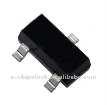
      As i am very new to PCB designing using CADENCE Allegro, i would like to know how to design foot print for SMD Transistor which is shown here. As per my knowledge, i have created foot print for micro controlles(QFP) whose pin numbers are same in four faces. But, here, we have only one pin in one direction and two pins in opposite direction.

     Please guide me how to design foot print for this. 

SMD Transistor


Constraint Region Via Use

$
0
0

Hello,

      I am working on a design that shall use two different micro-vias.  One shall have a 220um target land diameter for escaping dense .4mm pitch BGA's and the other shall have a standard 250um target land diameter. I have two regions on the board Default and Dense. When placing vias in the design the tool selects that appropriate via as called out by the region and all works well.

      As we have progressed throught the design we have decided to change the constraint region multiple times and we know have a mix of via spans (250um where there should be 220um's and vice versus). These offenders are not generating DRC errors? How do I configure the manager to flag any via that is out of compliance with Regional constraints? I thought this is what I had done but I must be missing something. All help would be greatly appreciated.

Thanks,

Clint

3D_viewing problem

$
0
0

Hi All,

 16.5 .S027 having a problem in the 3D view not showing the Z axis. Think it was working on earlier version, don't remember, but not working now. Open GL is enabled not sure where else to look. Free_viewer not showing 3D either.

Any suggestions?

Thanks

Mike

PHASE_TOLERENCE?

$
0
0

 Hi all,

 why we have adjust the phase tolerence between D+ and D-?

what is the difference between static and dynamic phase tolerence?

Anyone please guide me.,

Regards,

Karthik.

Windows 7 64 bit database problem

$
0
0

Hi .

I have Windows 7 64 bit , Office 2010 32 bit and Capture CIS 16.3 .

Problem is that it is impossible to connect to Part database .

Have you any solution ?

Increasing the size of icons

$
0
0

Hi, 

I'm using OrCAD Capture 16.5 the icon size is too small how to increase it. 

I deleted the "ini" file and then reinvoked the capture and have installed the latest hotfix also. 

It is happening only for capture. 

 please help me out.


Regards,

Vinay 

PDN ANALYSIS: Power network analysis failing

$
0
0

Hi,

While simulating for (decoupling analysis ) Power network analysis in PDN analyzer, am facing the following error. I have given all the load IC current, VRM and have assigned series elements resistance and inductance value.


"Failed to do the power network analysis for the given poweer/ground nets

Please check the analysis report"


CIS Derive database part Schematic part Libraries

$
0
0

 Hi all,

Can anyone tell me which sections of the Capture.ini file will populate the "Schematic Part Libraries:" and  the "Schematic Part:" drop down when you attempt a Derive Database Part operation please?

Left Click on Part.

Edit ->Derive Database Part.

Pop-up = "New Database Part"

"Schematic Part" -> Browse  "Schematic Part" and "Scematic Part Libraries" boxes are empty.

"Footprint" -> Browse .... under Footprint dropdown box shows Footprints contained in libraries pointed to by:

[Allegro Footprints]
Dir0=J:\PhysicsandAstronomy\Electronics\ORCAD\Allegro-PCB_Editor\Allegro Footprints

Dir1=J:\PhysicsandAstronomy\Electronics\ORCAD\Allegro-PCB_Editor\Allegro Padstacks

in the Capture.INI file and BackupCaptureCIS.INI

The "Configured Libraries:" box is empty.


All very curious, the tools for looking at the ini files seem rather "clunky" to say the least!


Many Thanks in advance.


Gareth


Integrating PSpice models with CIS Library

$
0
0

I am investigating adding PSpice modeling capability to existing CIS library database.  The best way I have seen it so far, is to obtain or create a PSpice model .lib or other ascii, and use that to create a symbol. Then basically place the symbol and copy the PSpice Template string to our existing library part.  The existing library part would then need a couple of additional properties that are called out in the PSpice template string, as well as the "Implementation", and "Implementation Type" property's. 

So here's my question, does anyone have any experience doing something like this, and know of a different way to do this? Can the Ascii pspice file / .lib be compressed to the "PSpice Template" string in any other fashion?

 thank you,

.color files

$
0
0

Does anyone know if it is possible to set a variable in the env file so that Allegro looks in one place for .color (view) files insted of the local directory.

Roger G


Function Swap(Gate Swap)

$
0
0

Hi,

I would like to Know the Procedure How to do Function Swap (Gate Swap)?in Allegro PCB Editor?

What are settings need to be done at the Schematic level?

Thanx in advance.

 Regards,

Sekhar

Problem seeing parts in capsym.olb e.g. OFFPAGELEFT-R

$
0
0

 I am following the "Example circuit creation" steps in the PSpice User Guide.

 I ran into a problem when I reached the point to place the OFFPAGELEFT-R symbol.

I added the capsym.olb library but, unlike my success with the previous libraries, no parts show up in the Part List when CAPSYM is highlighted.

I then tried searching for OFFPAGELEFT-R which led me to discover I can't find any parts with the search function. For example, I searched for D1N3940, which is already placed in my schematic, without success.

In case it matters, my capture.ini settings are supplied by my CAD group.


Locate a component by its reference on PCB - possible ?

$
0
0

Hello,

Locate a component on PCB (with zoom on it) by its refernce on is very useful function, especially on complex PCBs with thousands nets/components. But it seems that this feature is missed in OrCAD Allegro (or it's hiden by some sophisticated interface).

When I specify the component reference in the Find by Name entry (please, see the picture in attachment), nothing happens !

Moreover, when I move cursor out, the entered text disappears !!!

Is it bug, or I missed something ?

Thanks in advance.

Pavel.

Viewing all 5525 articles
Browse latest View live


<script src="https://jsc.adskeeper.com/r/s/rssing.com.1596347.js" async> </script>